
Booya SDR
Radio Receiver
Description
The
Booya SDR radio
receiver samples RF signals at 64MHz
or
100MHz with 16 bits and streams the sampled signal into PC
memory continuously
in real time. The Booya software demodulates the signals down
to baseband at
the full bandwidth. The Booya digitizer boards plug into the
Cypress USB 3.0
SuperSpeed Explorer Kit, included. The
Cypress
Explorer Kit
provides the USB 3 interface to the PC. The Booya SDR includes
an active Mini
Whip antenna to allow good radio reception in the 0 to 32 MHz
band. The
BooyaSDR free open source software on the PC provides a fully
functioning
SDR
receiver application
demonstrating the full Booya digitizer capability.
+12
Volt Antenna Ethernet Wire USB
3 to
Computer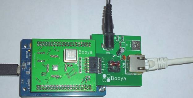
Figure 1. Booya SDR Digitizer Assembly
Features
64 MHz or 100 MHz 16 bit sampling rate
USB 3 Super Speed realtime input into PC memory
Features (continued)
Full speed decimation into 64 kHz bands in PC software
(1024 bands, 64kHz wide, spaced 32kHz apart )
Realtime demodulation of standard radio signals, AM, LSB, USB, CW
Any demodulation possible with software modification
Active Mini Whip antenna
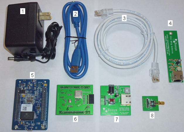
Figure 2. Booya SDR
Included Hardware
Items Included Hardware:
- +12 Volt Power Supply
- USB 3 Cable
- Ethernet Wire to Active Antenna
- Active Antenna
- USB3 Cypress Explorer Kit Board
- Booya Digitizer Board
with LTC2206 A/D Chip and 64 MHz clock or LTC2207 and 100
MHz clock
- Antenna Adapter Board
- Alternate RF Connector
Board
The Booya Digitizer product includes only items 2,5,6,8 above
Included Software, download from http://booyasdr.sf.net
- BooyaSDR Windows PC software application
- Windows Drivers
Required items:
- Windows PC with a USB3 Super Speed port (USB port marked SS), Windows 7 or better OS and a dual core PC should be sufficient
- Internet connection to obtain software
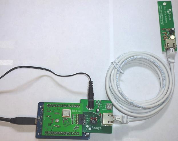
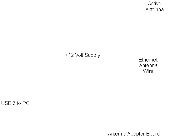
Figure 3. Assembled Booya SDR
SDR Hardware Setup Instructions
- Connect the Booya SDR hardware components as shown in Figure 3
A. Connect the digitizer board to the Cypress Explorer Kit USB3 board if not already connected. The pins are keyed to only fit one way
B. Connect the provided USB3 Cable between the PC Superspeed (SS) USB port and the Cypress Explorer Kit
C. Connect the Antenna Adapter Board to the Digitizer Board. Align the 6 pin connectors (Leave power pins bent upward unconnected)
D. Connect the Ethernet cable between the Antenna Adapter Board and the active antenna
E. Plug the +12 V power supply into the wall and connect the power cord to the Antenna Adapter Board
F. Hang the active antenna as high as possible in the room
- Verify the green power light on the bottom of the Cypress Explorer Kit board is on
- Download the latest version of the BooyaBinV1.0.zip software from http://booyasdr.sf.net
- Unzip the file to a convenient location
- Go into the
BooyaSDR/Driver/FX3Driver4Booya64-100 directory and click on
DriverSetup.exe with the Booya SDR board connected. The
driver should now be installed. This can be checked in the
Device Manager where the Cypress FX3 USB ... device should
appear
- Click on the booya64.bat or booya100.bat file to start the application. The program should complete its startup routine in a few seconds. The GUI user interface is intended to be self explanatory with a few pointers given under the Help menu. The program can also be started from the command line by changing directory to the bin folder and typing "booyasdr.exe X" where X is fx2_16, fx3_64 or fx3_100 depending on the hardware version attached
Troubleshooting
The Booya SDR is intended to work out of the box with minimum installation. Please follow the installation instructions above carefully. If you get the message "initFX3() failed" in the console window, the most likely reason is the board is not connected to the computer over the USB wire. Connect the board and restart the application. The BooyaSDR software must be quit and restarted whenever the board is reconnected or whenever the data stream stops otherwise. There is no facility to restart the data stream from within the application at this time.
Antenna Setup
A 7 ft Ethernet wire is included in this kit,
but reception
is improve using a longer Ethernet wire antenna connection. A
100 ft wire can
be used to put the active antenna out in the yard. The active
antenna needs to
be protected from the weather if placed outdoors. A small
plastic bag and tape
work fine to protect the active antenna temporarily. Placing the
active antenna
remotely on a long wire will normally improve reception
substantially by
reducing noise pickup from local sources and some studies
suggest that the long
wire act as part of the antenna increasing signal strength.
Please remember not
to connect the active antenna or antenna adapter to Ethernet.
While Ethernet
wire is used, there is no compatibility between the antenna
hardware and
Ethernet.
Alternate
RF Connector
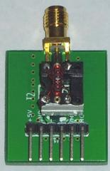
(A)
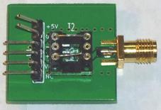
(B)
Figure 4. RF Connector, (A) with Stepup Signal Transformer (B) with Straight Through Connection
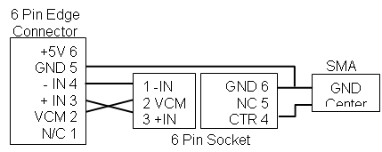
Figure
5. Schematic
of the Alternate RF Connector
The
RF connector
shown in Figure 4 can be used in place of the antenna adapter
board to replace
the custom ethernet connection with a standard SMA antenna
connector which can
then be connected to any antenna. The 6 pin connector is
intended to connect to
the digitizer in place of the antenna adapter. A schematic for
the RF connector
is shown in Figure 5.
Configuration
(A)
has the stepup transformer removed from the antenna adapter
board and place on
the RF connector board. The stepup transformer has a 64:1
impedance ratio and
does a good job of increasing the voltage amplitude of the RF
signal to put it
in the A/D range. Be sure to align the white mark on the side
of the
transformer with the white mark on the board to ensure it is
connected in the
stepup direction.
Configuration
(B)
has jumpers installed across the input connector to directly
connect the SMA
input to the A/D input if such a connection is desired. The
+5V and GND edge
connector pins should normally be bent up out of the way to
prevent one of the
A/D inputs from being grounded.
The
digitizer
board +5V and GND edge connector power output pins are
provided in case there
is a desire to power some input circuitry. Normally, however,
these two pins
should be bent up out of the way so that they are not
connected. The GND pin in
particular will ground one input of the LTC2206 A/D which is
intended to be
left floating. The middle +IN and –IN pins connect directly to
the LTC2206 chip
input on the digitizer board
Experimental Grade Product
While
every effort
has been made to maximize product functionality, product
improvement is
possible. The product does provide high quality basic
functionality and is
intended to work out of the box with minimum setup. Help is
available through
the contact information. Facility is provided for the user to
upgrade the
product as desired. Basic functionality is guaranteed.
Additional
Technical
Details and Development Setup
Additional technical details are provided in the section to more fully describe the product and to facilitate experimental product modification and development.
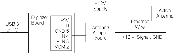

Figure
6. A Schematic
Version of the Connections Shown in Figure 3
Active Antenna
The included active antenna is based on the PA0RDT Mini Whip active antenna. While mini-whip performance remains controversial on the internet, it was found through simple experimentation that the active antenna substantially improves receiver performance for signal reception between 0 and 30 MHz. Therefore the additional feature of the active antenna has been included in this product.
Ethernet wire is used to connect the antenna adapter board to the active antenna as the default setup. Optionally an SMA adapter board is included for application flexibility. While coax is more commonly used in RF work, Ethernet was chosen in this application due to its high quality and high availability.
Ethernet Wire to Antenna
Ethernet wire is used to connect the active antenna to the antenna adapter. The signals carried by the Ethernet wire are RF signal down from the antenna, +12 Volt power up to the antenna and GND. The GND wire doubles as both the power ground and the signal ground.
Ethernet
Pin Signal
4 RF signal
3,5,6 GND
1,2 +12V
The table above shows the ethernet connector pin assignment.
Digitizer Board Connector
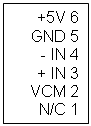
The diagram above shows the Booya digitizer board input connector.
RF input pins 3 and 4 connect directly to the LTC2206 A/D chip. No input circuitry has been put on the board to maximize user flexibility. VCM pin 2 is the LTC2206 voltage reference output for biasing the center tap of an input transformer. Pins 5 and 6 are GND and +5V power to power any user provided input circuitry. The Booya SDR 100MHz uses the LTC2207 A/D chip.
Software Application Development Setup
As this product is intended as a development component, source code is included on the website in the file BooyaSDRSource.zip for modification and development. The following steps will setup your computer for BooyaSDR application software development.
1. Download and unzip BooyaSDRSource.zip and wxWidgets.zip to a convenient location from the link on http://booyasdr.sf.net
2. Download and install Codeblocks 12.11 or later.
3. Open the Source\booyasdr.cbp project by clicking on it or from the File>Open menu in Codeblocks.
4. Tell Codeblocks where wxWidgets is by setting the wx global variable in Codeblocks.
a. In Codeblocks select Settings>Global Variables to open the Global Variables Editor dialog box
b. Hit the second from the top New button
c. Type wx in the box and click Ok
d. Set the wx variable base to the location of wxWidgets using the “...” button next to base or by typing the path in the blank next to base
e. Close the dialog
- The program should now compile. Test the compile by selection the Build>Rebuild menu and look for 0 errors in the Build log box
Firmware Development Setup
The FX3 firmware is provided for full user flexibility. Perform the following step to setup the firmware compiler.
1. Download and install the EZ-USB FX3 SDK v1..3.3 for Windows from http://www.cypress.com/file/139276/download (or for more FX3 firmware information and Linux go to EZ-USB FX3 Software Development Kit | Cypress )
2. Download the latest version of FX3firmwareV0.0.zip from http://booyasdr.sf.net and unzip to a convenient location.
3. Open the Eclipse EZ-USB FX3 SDK and import the slaveFifo project.
4. The firmware may be modified as desired using the SDK instruction.
5. To use the new firmware in the BooyaSDR.exe application, move the new firmware called slavefifo.img from the Debug directory in the firmware project to the BooyaSDR\Bin directory. You may want to make a backup copy the existing slavefifo.img prior to replacing it.
Booya SDR to WebSDR Comparison
The Booya SDR is roughly modeled on the Wide-band WebSDR which provides a 29 MHz bandwidth and can be seen on the web at http://www.websdr.org and http://websdr.ewi.utwente.nl:8901/.
The following table compares the Booya SDR and Wide-band WebSDR.
Wide-band
Booya SDR WebSDR
Operation System MS Windows Linux
PC connection USB 3 Ethernet
Bandwidth 32 or 50 MHz 29 MHz
User interface
PC
Web
browser
Contact
Please send any questions or comments to booyasdr@gmail.com.
License
This document
and the project
software source code are MIT Licensed. The MIT License is an
open source
license which MIT encourages others to use. No part of this
project was
produced by MIT (except for the fftw software package).
Details of the MIT
License are at:
https://opensource.org/licenses/MIT
https://en.wikipedia.org/wiki/MIT_License
The MIT License
itself is:
The MIT License (MIT)
Copyright (c)
2017 Booya
Corporation
Permission is
hereby granted,
free of charge, to any person obtaining a copy of this
software and associated
documentation files (the "Software"), to deal in the Software
without
restriction, including without limitation the rights to use,
copy, modify,
merge, publish, distribute, sublicense, and/or sell copies of
the Software, and
to permit persons to whom the Software is furnished to do so,
subject to the
following conditions:
The above
copyright notice and
this permission notice shall be included in all copies or
substantial portions
of the Software.
THE SOFTWARE IS
PROVIDED "AS
IS", WITHOUT WARRANTY OF ANY KIND, EXPRESS OR IMPLIED,
INCLUDING BUT NOT
LIMITED TO THE WARRANTIES OF MERCHANTABILITY, FITNESS FOR A
PARTICULAR PURPOSE
AND NONINFRINGEMENT. IN NO EVENT SHALL THE AUTHORS OR
COPYRIGHT HOLDERS BE
LIABLE FOR ANY CLAIM, DAMAGES OR OTHER LIABILITY, WHETHER IN
AN ACTION OF
CONTRACT, TORT OR OTHERWISE, ARISING FROM, OUT OF OR IN
CONNECTION WITH THE
SOFTWARE OR THE USE OR OTHER DEALINGS IN THE SOFTWARE.
More Booya64 Images
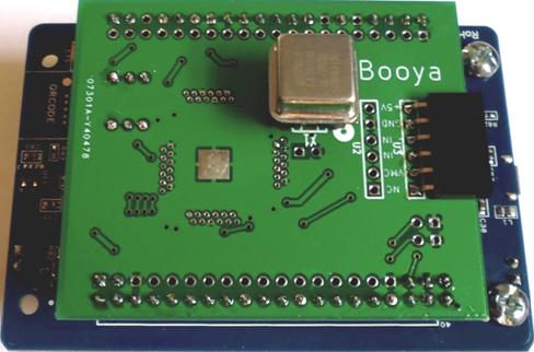
Figure 10. Booya64 Digitizer Mounted on FX3 Explorer
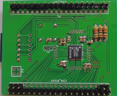
Figure 11. Booya64
Digitizer Bottom
Please send any questions or comments on this product to booyasdr@gmail.com.